An Introduction to surface roughness measurement
The mathematical definition of Surface Roughness parameters is very strictly defined by international standards. However, getting the “correct” result depends critically on the selection of a number of parameters that can be set by the metrologist.
Definitions
In any discussion of this type, we need to start with a few definitions. The important ones here are:
-
Roughness: A quantitative measure of the process marks produced by the creation of the surface and other factors such as the structure of the material. Not to be confused with Waviness or Form, which have longer wavelengths.
- Filter: A process to exclude wavelengths above or below a particular frequency. The measurement system is a mechanical filter. Software can perform mathematical filtering.
- Cut-off: The wavelength at which a filter becomes effective. For surface parameters we normally analyse wavelengths between an upper and lower cut-off: these are referred to as Ls or λs (shortest) and Lc or λc (longest). “Cut off” is also used synonymously with Sample Length as the sample length is always set to Lc. Bandwidth is the ratio of Ls to Lc.
So, where’s the problem?

fig1: profile showing a roughness wavelength of 0.25mm with an Ra of about 20μm
Look at figure 1. This hypothetical profile shows a roughness wavelength of 0.25mm with an Ra of about 20μm. If it were analysed with a cutoff (Lc) of 0.08mm the calculated Ra would be virtually zero. At Lc =0.25mm Ra would be about 10μm and at Lc = 0.8mm or 2.5mm you would get the “correct” result of Ra=20μm. If Lc were set to 8mm or more, the calculated Ra would increase, as the large waviness would then be included as well.
Basics
What are the key concepts in filtering a surface roughness profile? The most important concept is to know what you are dealing with – this will enable you to choose the appropriate stylus tip and filters. In most circumstances a single measurement will be made on the surface in order to assess the texture.
This measurement must be representative of the surface and appropriate to the purpose of the measurement (e.g. measured normal to the lay of the surface, or in the indicated direction).

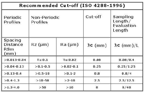
cut-off-chart
(Recommended cut-offs for different surface finishes)
Selection of Lc/ λc
The choice of λc filter will depend on the process being assessed. There are a number of guidelines available, for example ISO 4288-1996 (see table below). However the choice of cut-off should be made after consideration of the spacing of the profile features (peaks and valleys) caused by the machining process, denoted RSm. As a rule of thumb λc should be set to about five times this spacing.
Selection of Ls/λs/Bandwidth
ISO introduced the concept of “bandwidth” in the late 1990’s. Under this regime the shorter wavelengths used in surface roughness analysis are constrained by a short wave filter (know as the λs filter – see ISO 3274:1996).
The bandwidth is then limited in a controlled way that relates directly to surface features, rather than being limited by the bandwidth of the measuring system. The ISO recommendation is to use a bandwidth of 300:1 wherever possible.
The smallest λs available will be dependent on the data spacing available in the raw profile: for an instrument with 0.25um data spacing, the smallest λs that can be represented is 1.25um. The λs filter should be chosen so that it does not attenuate wavelengths that are likely to be introduced by the machining process. The recommended combinations of λc, λs and stylus tip radius are shown in ISO 3274:1996.
Filter selection
In general the Gaussian filter is preferred as it is phase correct and has a fast roll-off without “ripple”. Taylor Hobson Ultra software also offers 2CR and 2CR-PC (phase corrected) filtering. These should only be used when you need backward compatibility with results from older instruments.
The effect of choice of filter is more subtle, causing changes of “only” a few percent in roughness parameters. However, these can be significant when establishing consistency across sites or between instruments.C
Reproduced with kind permission of: Taylor Hobson Ltd
jul2017
